When pin 2 of the printer port is set high(1), BC548 will conduct, allowing current to flow through the relay. The relay then activates the strobe lamp and piezo buzzer. When pin 2 is set low(0), BC548 turns off the relay and stops the strobe/buzzer. 1N4148 protects the LPT port from accidental reverse polarity. 1N4004 absorbs transient current induced by the relay switching on/off.
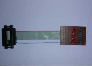
Parts
-----
1   1N4148 diode
1   1N4004 diode
1   BC548 NPN transistor
1   9V relay
1   mini piezo buzzer (3-16V)
1   blue mini alarm strobe (12V)
1   9V DC adapter
1   DB25 male plug
Pin 2 - 9 = Data 0 - Data 7 (output)
Pin 18 - 25 = Ground
C++ Control Program
setport is a C++ program that writes a bit pattern to LPT1 to toggle data output lines high(1) or low(0). It uses an NT driver Tinyport 2.0(included in zip) which allows user mode programs to access the parallel port directly. This program has been tested under Windows NT 4 only. To control the alarm circuit, only pin 2(Data 0) needs to be set/cleared. Hence the bit pattern is simple - 1 or 0. Download the software here.
Java Control Program
To control the alarm circuit from a Java program in Windows 2000/XP, download the following:
ParallelPort class
UserPort driver
- Unzip parport-win32.zip into your classpath directory. You should end up with eg. C:\classes\parport...
- Unzip UserPort.zip under parport. You should end up with eg. C:\classes\parport\UserPort...
- Copy parport.dll to your JDK bin directory.
- Copy UserPort\UserPort.SYS to %WINDIR%\SYSTEM32\DRIVERS
- Run UserPort.EXE, add or remove required addresses(default: parport base at 0x378), click Start, Exit
- The following program has been tested under JDK 1.4.2_04.
import parport.ParallelPort; class SetPort { public static void main ( String []args ) { int aByte; ParallelPort lpt1; if (args.length != 1) { System.out.println("Usage: java SetPort NN where NN=00-FF(hex bit pattern to send to LPT1)"); System.exit(1); } else { lpt1 = new ParallelPort(0x378); // 0x378 is normally the base address for the LPT1 port aByte=Integer.parseInt(args[0],16); lpt1.write(aByte); // write a byte to the port's DATA pins System.out.println("Output to port: " + aByte); } } } - Example usage: java SetPort 1 - this will set pin 2(Data 0) high on the parallel port.
- Example usage: java SetPort 0 - will set all pins low on the parallel port.